Estimating 3D Coordinates From an RGB Image
In this post, I will detect objects in an image and map them to their 3d world coordinates. I will be using my laptop’s webcam for aquiring the images of the object and OpenCV for all the image transformations.
You can find the complete code for this task in this github gist.
Pinhole camera model
For this post, I will assume a pinhole camera model. With a pinhole model, 3D points in the world frame (XYZ) are projected to the image plane (uv) using the transformation:
This transformation can be seen as a perspective projection followed by a 180° rotation in the image plane.
Camera calibration
The matrix K, called the camera intrinsics matrix, maps 3D coordinates in the camera frame to the 2D image plane.
I started by printing the chessboard pattern from OpenCV source code folder and took a few images with my webcam (I used 10).
I then used Matlab’s cameraCalibrator to estimate my intrinsics matrix. I found this tool much more powerful than OpenCV’s alternative.
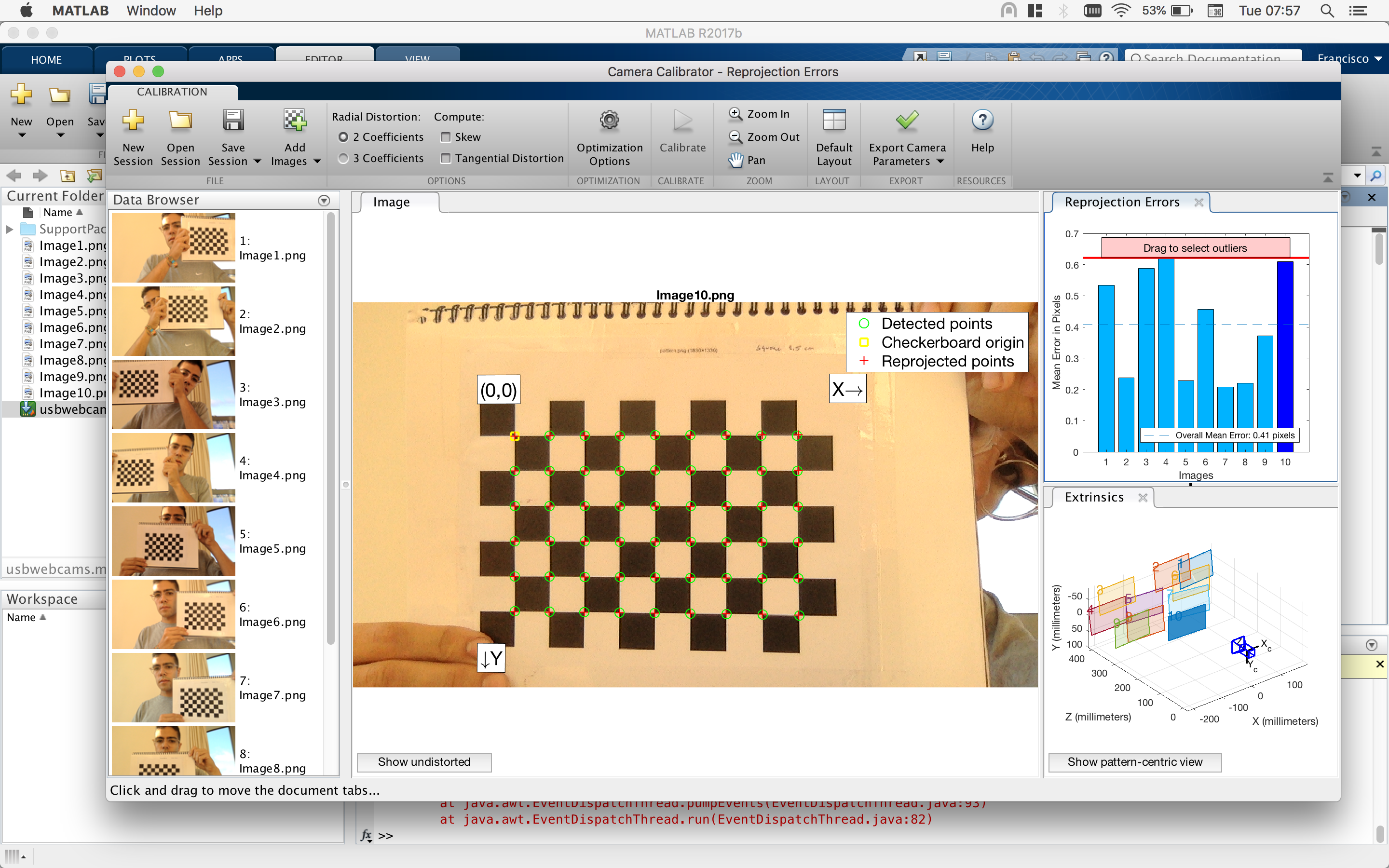
Lastly, I exported the computed camera intrinsics and distortion coefficients and loaded them on my OpenCV program.
camera_matrix = np.array([[1046.0, 0, 657.9], [0, 1043.8, 362.0],[0, 0, 1]])
dist_coeffs = np.array([0.111412276912893, -0.270066987227198, 0, 0])
Camera extrinsics
The camera extrinsics matrix describes how points in the frame map to the camera frame and assumes the form:
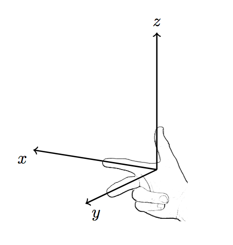
or simply [R|t] . In order to simplify this exercise, the camera frame will be placed in the origin of the world frame and share the same axis. OpenCV uses a right-handed coordinate system, so the world and camera frames both should use the same, as there is no rotation that can transform a right-handed coordinate system into a left-handed one.
The rotation part of the extrinsics matrix becomes the identity matrix, R = I, as the axis of the world frame will correspond to the axis of the camera frame.
The translation part of the matrix can be obtained with t=-RC, where C is a column vector describing the location of the camera in the world frame. For this exercise, let’s have t be a column vector of zeros.
Undistorting the image
Real lenses usually have some distortion, mostly radial distortion and slight tangential distortion (dist_coeffs). So before we do any measurements on the images obtained with our camera, we should undistort the image:
frame_undistorted = cv2.undistort(frame, camera_matrix, dist_coeffs)
Determining distance to object in meters
The projection done when using the pinhole camera model is a one way transformation: there are an infinite number of points in world space that all map to the same point in the 2D image.
But if somehow we know the depth Z of the object from the camera, we can calculate X and Y using the first equation first above.
Because the real dimensions of the detected object are known, its distance to the camera (in centimeters), Z, can be computed with:
Z = diagonal_cms * focal_length_pixels / measured_diagonal_pixels
wherediagonal_cms is the real dimensions of the object in centimeters and measured_diagonal_cms is the diagonal of the bounding of the detected object in pixels.
If the image has been resized, measured_diagonal_pixels should be scaled accordingly.
By replacing the known value of Z in the pinhole camera equation, we can now calculate the X and Y world coordinates from the image coordinates using:
The result is in homogeneous coordinates, so X and Y can then be obtained by dividing by the third row.
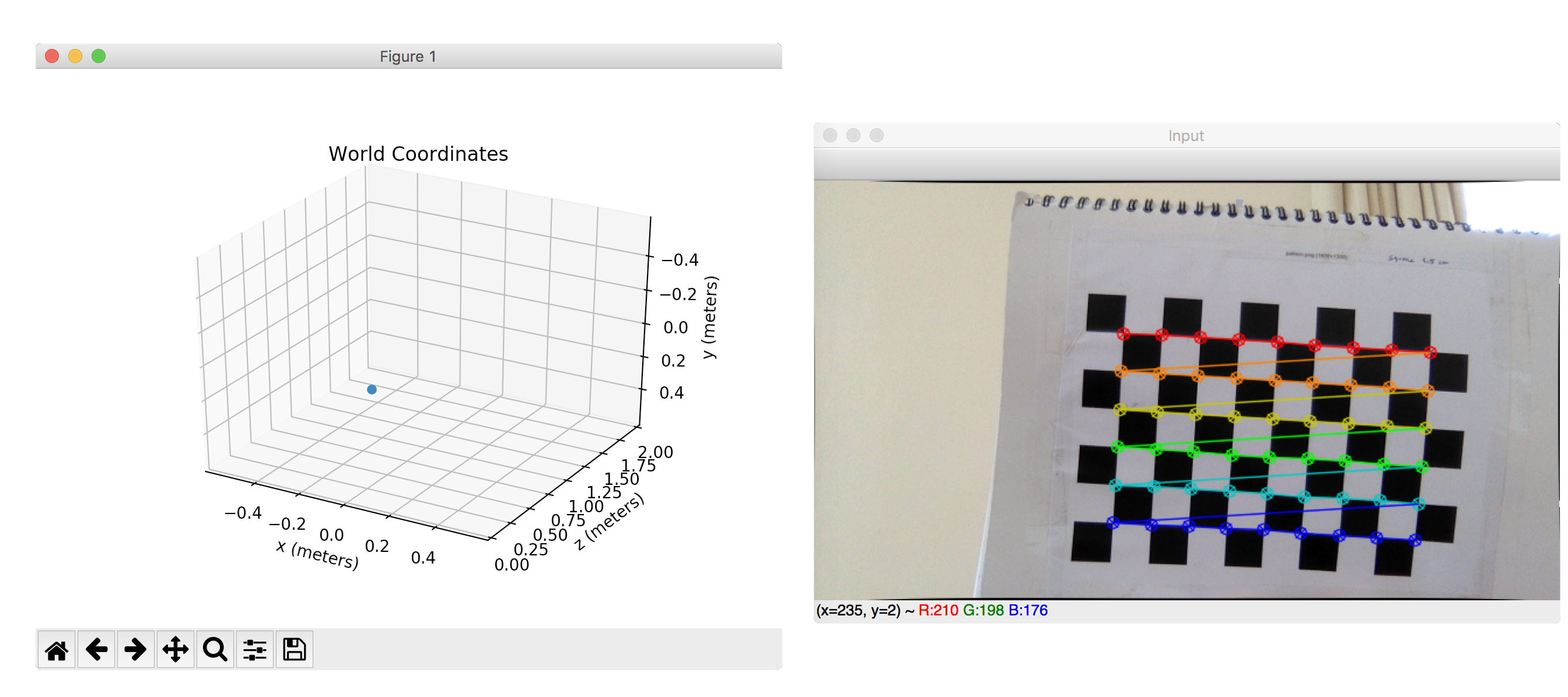
The provided gist also includes the code to plot real world coordinates in real time (camera is placed in the plot origin):